|
|

 |
 |
 |
 |
 |
 |
|
|
|
INSTALLATION INSTRUCTIONS
Introduction
In most installations, the Mini-Clik II acts as a switch to break the circuit to the solenoid valves of the irrigation system when it has rained. This allows the timer to advance as scheduled, but keeps the valves from opening the water flow. Once the Mini-Clik II has dried sufficiently, the switch closes again to allow for normal operation.
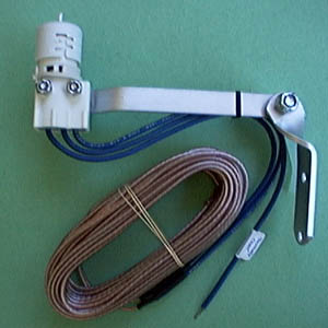
The Mini-Clik II has three blue wires coming out of it. Two are connected to a 25 ft. extension, and the third center one is left disconnected. This center blue wire is the "normally-open" lead of the switch and is not used in most installations. The remaining two extension wires are colored (one "silver" tinned, the other natural copper); however, in the following instructions it will not matter which wire is connected at a given junction.
Mounting
Using the screws provided, mount the Mini-Clik II on any surface where it will be exposed to unobstructed rainfall, but not in the path of sprinkler spray. The switch-housing portion must be upright (as pictured), but the swivel bracket can be moved for mounting on any angled surface. Loosen the locknut and screw before swiveling bracket, and then re-tighten, |
 |
Helpful hints for mounting:
A. When looking for a suitable location such as on the side of a building or a post, the closer the Mini-Clik II is to the controller, the shorter the wire run will be. This will also minimize the chance for wire breaks.
B. The ideal location for mounting is not always the most practical location. In the case where a compromise must exist (such as a low location on a side wall rather than the preferred high location), note that the Mini-Clik II will still work as it will always receive some rainfall-it just will not be as accurate in its gauging as it could be.
C. As described in the "Operation" section of this manual, 'reset rate' refers to the amount of time it takes the Mini-Clik II to dry out sufficiently for the sprinkler system to be allowed to come back on. The mounting location will affect this rate and should be taken into consideration should extreme conditions exist. For example, mounting the Mini-Clik II on a very sunny, southern end of a building may cause the Mini-Clik II to dry out sooner than desired. Similarly, mounting on the northern end of a building with constant shade may keep the Mini-Clik 11 from drying soon enough. Some experimentation and use of the "vent ring" (as described later) will usually yield satisfactory results.
Once the Mini-Clik II is mounted, run the wire to the controller, and fasten it every few feet with wire clips or staples for best results. If an extension to the wire provided is needed, use the following table to determine the minimum wire gauge needed:
If the extension needed is;
25-50 ft. use 20 AWG,
50-100 ft. use 18 AWG,
100 ft. or more use 16 AWG Wiring
Wiring
Important: The Mini-Clik II Model 502 is sold and designed for hook-up to 24 Volt irrigation controllers only. For wiring to 110V or 220V irrigation controllers please consult your distributor or this factory. All wiring must conform to National Electrical Code or applicable local code.
The two most common situations are shown below. For non-standard wiring situations, please consult your distributor or request our "Non-standard" wiring packet.
A. 24 Volt Solenoid Valves Only (No booster pump) (See Diagram A) |
 |
B. 24 Volt Solenoid Valves with Booster Pump (See Diagram B) |
 |
Twist together these two wires along with one wire from the Mini-Clik II and secure with a twist on wire connector. Attach the other wire of the Mini-Clik II to the "Common" terminal on the controller. Note: The pump circuit output must be 24 Volts in this situation. Do not proceed if 110V.
Operation Check to Verify Correct Wiring
Turn on one station of the irrigation system that is visible while you are in reach of the Mini-Clik II. Manually depress the spindle at the top of the Mini-Clik II until you hear the switch "click" off. The sprinkler station should stop instantaneously. If it does not, check wiring for correctness. It is not necessary to "wet" test the Mini Clik II, although it will test the operation fine, if desired.
Adjustments and Operation
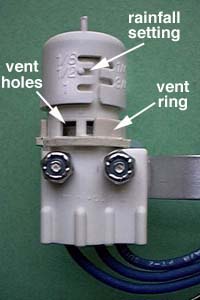
The Mini-Clik II can keep the irrigation system from starting or continuing after rainfall quantities of l/8", l/4", l/2", 3/4" or l". To adjust it to the desired shut-off quantity, rotate the cap on the switch housing so that the pins are located in the proper slots. (See Diagram C) Do not forcibly twist the cap as this might break the pins. |
 |
The time that it takes the Mini-Clik II to reset for normal sprinkler operation after the rain has stopped is determined by weather conditions (wind, sunlight, humidity, etc.). These conditions will determine how fast the hygroscopic discs dry out, and since the turf is also experiencing the same conditions, their respective drying rates will roughly parallel each other. So when the turf needs more water, the Mini-Clik II is already reset to allow the sprinkler system to go at the next scheduled cycle.
There is an adjustment capability on the Mini-Clik II that will slow down the reset rate. By turning the "vent ring" (see Diagram C) to completely or partially cover the ventilation holes, the hygroscopic discs will dry more slowly. This adjustment can compensate for an "overly sunny" installation location or peculiar soil conditions. Experience will best determine the ideal vent setting.
Bypassing the Sensor
Should you desire to bypass the operation of the Mini-Clik II for any reason (i.e., turn on your system even though the Mini-Clik II has shut "off" due to rainfall), there are two simple ways to do this. The first is to add our Bypass Switch Box Model 202. This mounts on or next to the controller, and by simply moving the switch, the Mini-Clik II is bypassed. The second method is to go to the Mini Clik II and raise the "cap" a couple of settings higher or completely remove it. This takes the pressure off the switch button, which allows the valve circuit to close again. Note: using the "manual" switch on the controller will not bypass the sensor.
MAINTENANCE
There is no required maintenance for the unit. The Mini-Clik II does not have to be removed or covered for "winterizing" purposes. All parts are easily replaceable if they become damaged or lost. The spindle assembly is designed to stay with the cap. Do not pull them apart. (See Parts Diagram D) |
 |
Troubleshooting
Follow these simple checks first before assuming the unit is bad and replacing it.
System will not come on at all:
A. First, check to see that the 'Mini-Clik II discs are dry and the switch "clicks" on and off freely by pressing the top of the spindle.
B. Next, look for breaks in the wire leading to the Mini-Clik II and check all wire junctions.
C. Finally, if the Mini-Clik II is dry and the wire leading to it is good, check the Mini Clik 11 switch by nicking the insulation of the two "outer" wires near the unit to expose copper. Turn one sprinkler station on, and apply a "jumper wire" across the two exposed wires- If the sprinkler now comes on, the switch is bad. Wrap all nicked wires with electrical tape.
System will not shut off even after heavy rainfall:
A. Check wiring for correctness. (See "Operation Check to Verify Correct Wiring".)
B. Check sensitivity setting on Mini-Clik II-move cap to more sensitive setting- The Mini-Clik II is an accurate rain gauge and can be verified by setting up a "tube" type rain gauge in the same vicinity and making periodic readings.
C. Is the rainfall actually hitting the Mini-Clik II? Check for obstructions to rainfall such as overhangs, trees, or walls.
GUARANTEE
Mini-Clik II Rain Sensors are guaranteed against defective workmanship and material when properly installed and used. This guarantee is valid for a period of five years from the date of purchase. The guarantee is limited to the repair or replacement of defective controls. All alleged defective Mini-Clik II Rain sensors must be returned to us or your distributor with transportation charges prepaid.
Manufactured under U.S. Patent No. 3,808,385.
| |||||||||